1. Welcome to 4Runners.com!

    You are currently viewing as a guest! To get full-access, you need to register for a FREE account.

    As a registered member, you’ll be able to:
    • Participate in all 4Runner discussion topics
    • Transfer over your build thread from a different forum to this one
    • Communicate privately with other 4Runner owners from around the world
    • Post your own photos in our Members Gallery
    • Access all special features of the site

Where should I connect to the fuse box for light bar install

Discussion in '5th Gen 4Runners (2010-2024)' started by Nelson-ohio, Aug 2, 2023.

  1. Sep 23, 2023 at 2:29 PM
    #31
    Thacrow

    Thacrow New Member

    Joined:
    May 30, 2021
    Member:
    #21719
    Messages:
    1,565
    Gender:
    Male
    NorCal
    Vehicle:
    2021 ORP
    Speed holes
    I bought the bracket for a blue sea setup and made it work. If you wanna scroll through my build thread I point out cutting some material off the bracket so it can be more easily bolted to the inside fender.

    On my phone away from home here so it's hard to dig up that picture.

    Edit:
    because the relay box was in the way of my ratchet and socket I had to remove the bracket and cut this rectangle out to fit a spanner. so Maybe do that or locate the relay box further from those bolts.

    20220928_170213.jpg
     
    Last edited: Sep 23, 2023
    Saker likes this.
  2. Sep 26, 2023 at 8:25 PM
    #32
    Nelson-ohio

    Nelson-ohio [OP] New Member

    Joined:
    Mar 15, 2023
    Member:
    #31784
    Messages:
    14
    Gender:
    Male
    Vehicle:
    2023 4Runner Off Road Premium
    Working on it
    Thacrow: I understand using 1 of the relay to power up all the AOB switch lights, just want to understand how the wiring would run. I found a fuse spot under the dash (Labeled IGN), installed an "add a fuse" thing, basically the same as what you showed in one of the pictures. Will use a 3A fuse for the new circuit, I believe that's enough. So this wire will be hot when IGNITION is ON, which I will run it to the RELAY post #86, which will power up the RELAY when IGNITION is ON. Post 30 will be connected to the battery with correct fuse, in this case, 5A should be enough, since I only want to light up the switches. I believe I'm correct so far?

    Something I need to confirm, I'm not sure if POST 87 should be connected to AOB 's BLUE/WHITE wire or the RED wire(see Saker's diagram below):
    - The RED wire gives power to the AOB so it can power up any RELAY when AOB is pressed.
    - The BLUE/WHITE is for illumination. If POST 87 goes to BLUE/WHITE, the switch light will turn on when IGNITION is ON, but I will still need power to the AOB's RED wire, correct?
    - Or, do I just feed from post 87 to both the RED and BLUE/WHITE wire.

    Trying to make sure I have a clear understanding how to run the wires first.


    [​IMG]
     
  3. Sep 26, 2023 at 9:07 PM
    #33
    Thacrow

    Thacrow New Member

    Joined:
    May 30, 2021
    Member:
    #21719
    Messages:
    1,565
    Gender:
    Male
    NorCal
    Vehicle:
    2021 ORP
    Speed holes
    taking a step back and re-reading all your posts - how many accessories are you going to power? Anything more than the light bar?

    Edit: I do remember you have the thread regarding the winch. Could put that on a switch.

    If it's only the light bar, the easiest thing would be to use one relay for the light bar and then put your factory style push button on the add-a-fuse.

    Where I think it makes sense to use a relay to power your switches: if you are going to have multiple accessories on switches and one or more of those accessories doesn't need a relay (the amp draw is less than what the switch can handle so don't need a relay). I chose to have a relay power my switches because I have 3 switches (which is not much draw) but I planned to add some small side roof rack lights (low amp draw so the switch doesn't need a relay) and I was intending to add maybe 4 or 5 more switches in the future and just wanted expand ability.

    That said, if you only are going to have the light bar then I'd run the factory style switch off the add-a-fuse.

    in Saker's that diagram

    30 - connect to battery positive (in your case this positive would be coming off your fuse block you have on that bracket and the fuse block would have a fuse for the positive wire feeding it)
    86 - your switch trigger. Blue is the universal color for switched power. So 99.9% chance it's the blue wire but you can take a 9 volt battery and any light you have laying around and test this.
    85 - ground
    87 - positive to your accessory for which the switch is turning on; the light bar


    BLUE/WHITE wire or the RED wire(see Saker's diagram below):
    - The RED wire gives power to the AOB so it can power up any RELAY when AOB is pressed.
    Ther'es 3 red wires.
    1Positive wire to the factory style switch which is from the add-a-fuse.
    2:battery positive to terminal 30 on the relay.
    3: terminal 87 from relay to positive wire on your light bar
    - The BLUE/WHITE is for illumination. If POST 87 goes to BLUE/WHITE, the switch light will turn on when IGNITION is ON, but I will still need power to the AOB's RED wire, correct?
    blue/white to illumination circuit (this is coming out of the factory style switch right?) just means this is your trigger to turn your light on and is plugged into the 86 pin on your relay telling your relay to then give power to the light bar when you press the button
    - Or, do I just feed from post 87 to both the RED and BLUE/WHITE wire.
    87 goes to the positive wire on your light bar and nothing else.
     
    Last edited: Sep 26, 2023
    T in Texas and Saker like this.
  4. Sep 27, 2023 at 5:40 PM
    #34
    Nelson-ohio

    Nelson-ohio [OP] New Member

    Joined:
    Mar 15, 2023
    Member:
    #31784
    Messages:
    14
    Gender:
    Male
    Vehicle:
    2023 4Runner Off Road Premium
    Working on it
    Thank you Thacrow. I will go over this and think carefully. Still waiting for the relay box from Amazon, has a few days to figure this out.
     
    Thacrow likes this.
  5. Nov 20, 2023 at 10:58 AM
    #35
    kojak

    kojak New Member

    Joined:
    Sep 19, 2023
    Member:
    #35749
    Messages:
    281
    Gender:
    Male
    Vehicle:
    21 SR5P 4x4
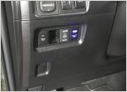
    PXL_20231120_172917256.jpg

    I just stuck it here to see how I like it, don't have anything wired up yet.
     
  6. Nov 21, 2023 at 12:17 AM
    #36
    Thacrow

    Thacrow New Member

    Joined:
    May 30, 2021
    Member:
    #21719
    Messages:
    1,565
    Gender:
    Male
    NorCal
    Vehicle:
    2021 ORP
    Speed holes
    Pretty buttons
     
  7. Nov 21, 2023 at 3:45 AM
    #37
    Kimbro

    Kimbro New Member

    Joined:
    Nov 21, 2023
    Member:
    #36840
    Messages:
    7
    Gender:
    Male
    First Name:
    Joe
    Vehicle:
    2023 4Runner TRD ORP
    Saker has a very well thought out, put together build!
     
    Saker likes this.
  8. May 20, 2024 at 8:05 PM
    #38
    Nelson-ohio

    Nelson-ohio [OP] New Member

    Joined:
    Mar 15, 2023
    Member:
    #31784
    Messages:
    14
    Gender:
    Male
    Vehicle:
    2023 4Runner Off Road Premium
    Working on it
    OK, here is the final update on this. It took me a while, that's always been my problem, get side tracked too much. Any ways, a big thanks to everyone who gave me ideas and suggestions. Especially Thacrow and Sakar.

    Here are some pictures of the final setup.


    image6.jpg

    This this the back side of the mounting plate, I painted it with plastic dip coating, like 6 thin coats. Came out OK. I changed the layout from the original design, so some cutoff and bolt holes are not used. Didn't want to buy a new plate and cut it out and everything.


    image5.jpg

    This is the top side with all the pieces mounted. There are 6 relays in this box, I'm only using 2. 1 from the accessories switch that turns on and power up the factory style push button. I can power up 3 of the buttons if needed from this relay. The other relay is for the front light bar.

    image4.jpg

    I was testing the setup to make sure it worked the way it should. Everything looked OK.

    image1.jpg

    This is the finished setup. Taped some wiring information on the relay box "inside and out" so I can remember what I did.

    image3.jpg

    Slightly different angles.

    image0.jpg

    I think this is a wrap for this one.

    Again, a big thanks to everyone.
     
    Saker likes this.

Products Discussed in

To Top