

-
Welcome to 4Runners.com!
You are currently viewing as a guest! To get full-access, you need to register for a FREE account.
As a registered member, you’ll be able to:- Participate in all 4Runner discussion topics
- Transfer over your build thread from a different forum to this one
- Communicate privately with other 4Runner owners from around the world
- Post your own photos in our Members Gallery
- Access all special features of the site
 2021 TRD Pro Overhead console removal
 Another Dealer Scam
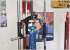 Any suggestions for a good brand of spring compressors that won't kill or maim me?
 Portable CO2 Tank
 0W-20 In The Texas heat??
 IPhone 12 Pro Max Charging Solutions
Heated steering wheel mod - success!
Discussion in '5th Gen 4Runners (2010-2024)' started by Emmantik, Nov 7, 2023.
Page 3 of 3
Page 3 of 3


