

-
Welcome to 4Runners.com!
You are currently viewing as a guest! To get full-access, you need to register for a FREE account.
As a registered member, you’ll be able to:- Participate in all 4Runner discussion topics
- Transfer over your build thread from a different forum to this one
- Communicate privately with other 4Runner owners from around the world
- Post your own photos in our Members Gallery
- Access all special features of the site
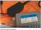 Let's talk about headlights...
 Rock Light Suggestions - Pure Wite
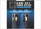 921 Reverse Bulb Thread
 03 3rd Brake Light In The Wing
 OEM LED Headlight Bulb Replacement
DD w/backlight OEMish switch
Discussion in 'Lighting' started by scottiezilla, Feb 28, 2024.


