

-
Welcome to 4Runners.com!
You are currently viewing as a guest! To get full-access, you need to register for a FREE account.
As a registered member, you’ll be able to:- Participate in all 4Runner discussion topics
- Transfer over your build thread from a different forum to this one
- Communicate privately with other 4Runner owners from around the world
- Post your own photos in our Members Gallery
- Access all special features of the site
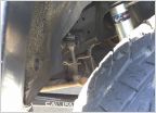 Installing 4th Gen Sway Bar Links with Heim ends
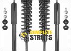 4th generation strut replacement
 What's up
 Timing belt coming up
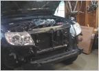 How To: 4th Gen V6 Radiator Replacement/Tranny Cooler Install
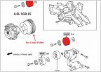 Dropped Nut Landed Inside Fan Clutch Pulley
4th gen ARB onboard compressor mounting bracket-CHEAP how to
Discussion in '4th Gen 4Runners (2003-2009)' started by MI-FL off roader, Apr 14, 2020.


